Honda Civic = 0.16 L/min at 60mph: ~28mpg
Baseline ranger measures at ~24mpg in mostly freeway driving
Water injection
I’m hoping that adding water to the intake air of the engine will do a few things
-
Swallow a lot of combustion heat by changing phases, thus reducing exhaust temperatures which will allow the engine to run lean without producing NOx and similar
-
Expand more with temperature than dry air, producing more power for a given amount of energy
I’ve done very little research to determine if either of these things will happen
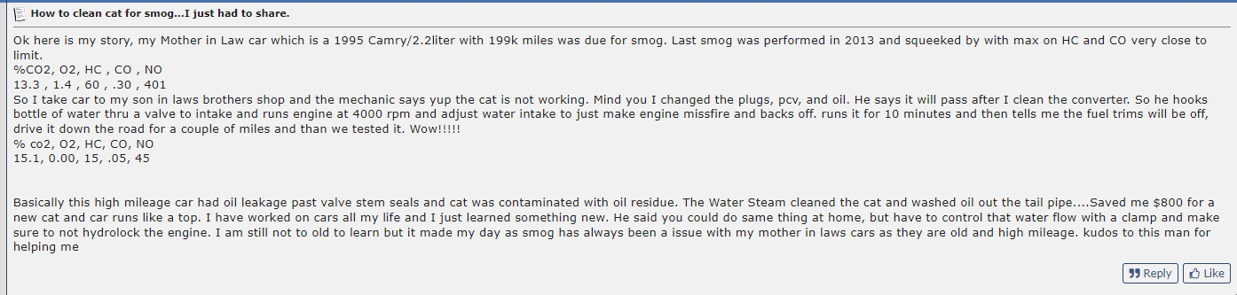
I’ve also been having some troubles passing smog due to slightly high hydrocarbon production
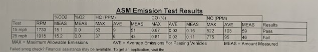
Some people on the internet seem to think that ultra high temperature steam (like this will produce) can somehow “clean” the catalytic converter???
Mechanical
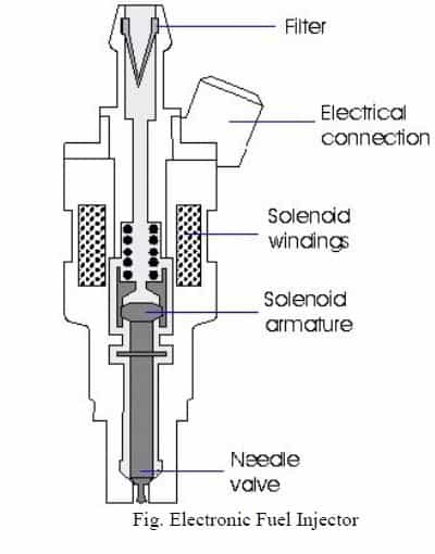
I bought a high pressure water pump and a fuel injector along with the appropriate electrical connector
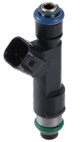
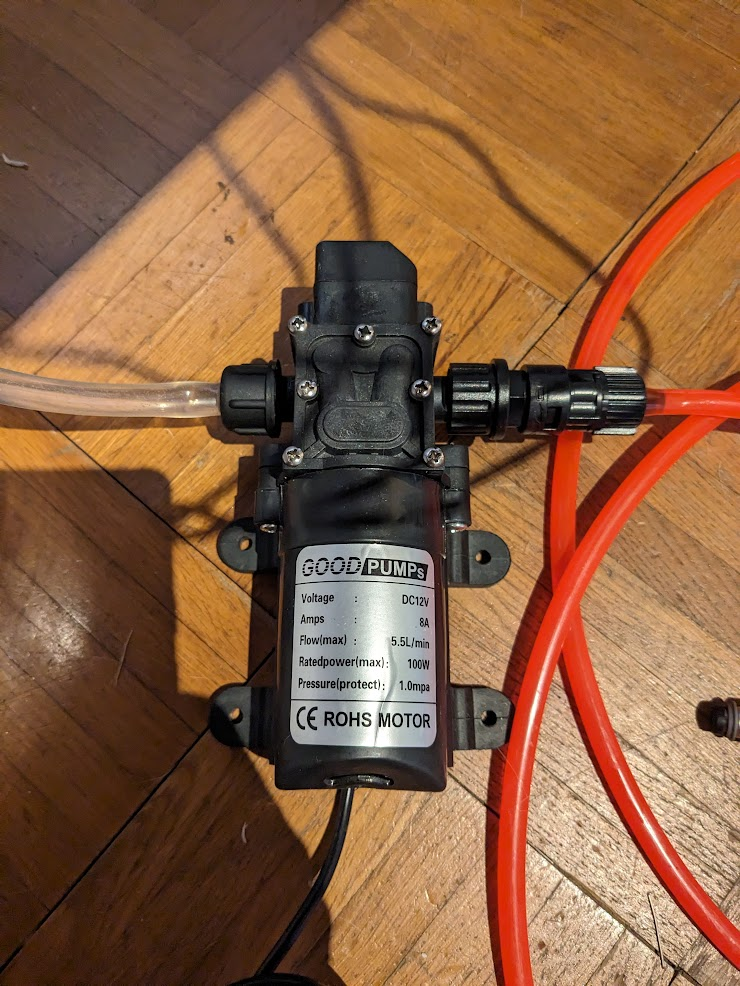
I took the input o-ring off the fuel injector, and the hose that came with the pump fits fairly well over the body of the injector
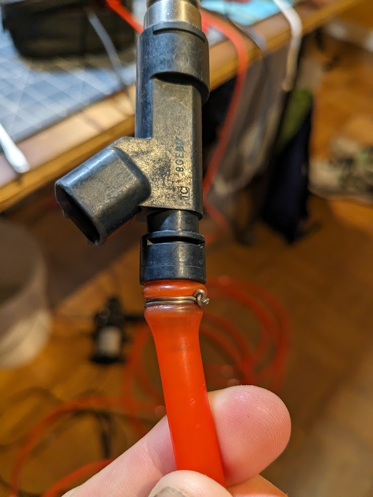
This ended up being leak free enough to test the injector, which worked as expected.
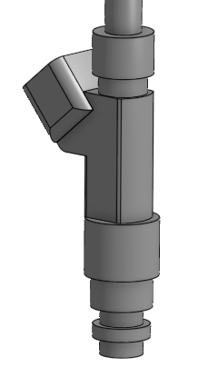
I modeled the injector in CAD
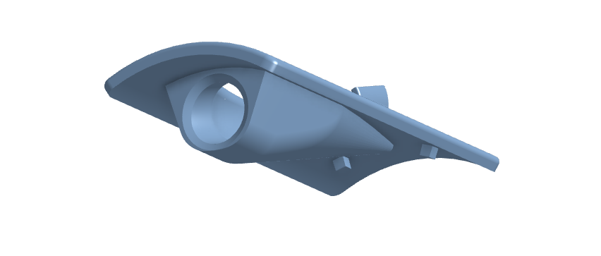
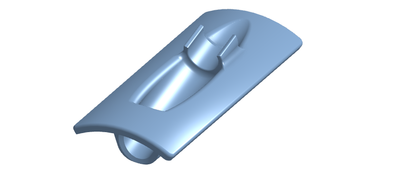
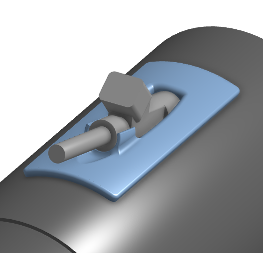
Then I modeled a well sealed mount for it which will shoot the water in the direction of the air-flow in the intake. This piece will strap over a rectangular hole which I will cut in the round intake tube:
It all goes together something like this:
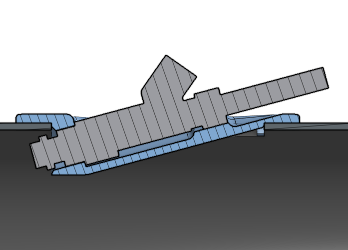
I’m planning to use foam adhesive to both mount it and as a seal, with zip ties wrapped around the intake pipe to hold mounting pressure.
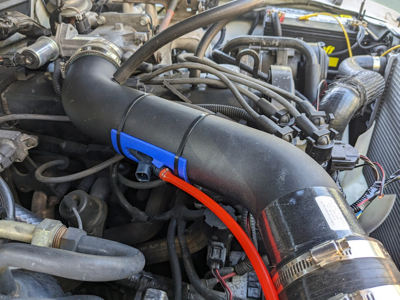
I cut the rectangular hole in the aluminum intake pipe using a rotary tool and a 2 flute endmill. I do not recommend this method. Here’s how it all went together:
Electrical / Control
I need to get a microcontroller running the water injector so I can characterize it’s flow. I’m especially curious to see if it’s open and close time will be significant, since there is mechanical movement going on inside.. Something like this:
Actuation time is important to me because I know I will need to tie the amount of water being injected to at least the engine RPM and probably also the mass air flow rate or throttle position - I shouldn’t just open it once per engine revolution because then one cylinder might get hit with more water than another. So I have 2 options:
-
Open it 4 times per engine revolution, each 90 degrees phase offset, which I know it can do since that’s exactly what it’s normally doing in an engine
-
Give it some comparably fast PWM to get a smaller but still continuous flow
If I am forced to do the first one I will need to find a clean signal for the engine’s rotation which is in-phase, which I don’t have - I’d need to tap into the crankshaft position sensor (CKP), which is an analog hall effect sensor and with the amount of noise in the engine bay, I’d need to do some serious analog and digital filtering.
This is why I’d much rather do the later, but I need to make sure the injector can open and close fast enough or stay in a halfway spot reliably, and that while doing so the fineness of the mist it puts out (atomization) is still good.
I’ll also either connect into the OBD2 port (which on my model year isn’t CAN, but rather annoyingly is SAE J850 PWM) for MAF/throttle, or I’ll tap the wire from the MAF to the ECU.. I need to figure what sort of signal it is first - I know it’s analog but I’m not sure if it’s some scuffed non-linear thermocouple/heater current thing or if it’s a nice clean voltage output. The OBD port is really slow with the ELM327 adapter I have (like 900ms per update) so I’m not sure if that will work at all.
I traced and tapped the wires going to the CKP in an accessible location using insulation displacement connectors. This tap will later become a permanent connection, so I tried to do a nice job.
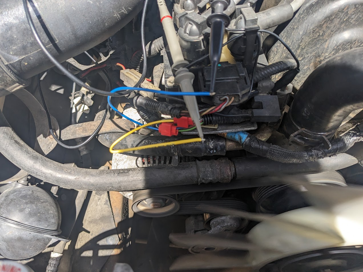
The 2 wires associated with the CKP in the schematics are marked as + and -, and are a twisted pair. This makes me think the CKP outputs a differential signal.
This is what the crankshaft position sensor’s signal looks like, referenced to chassis ground:
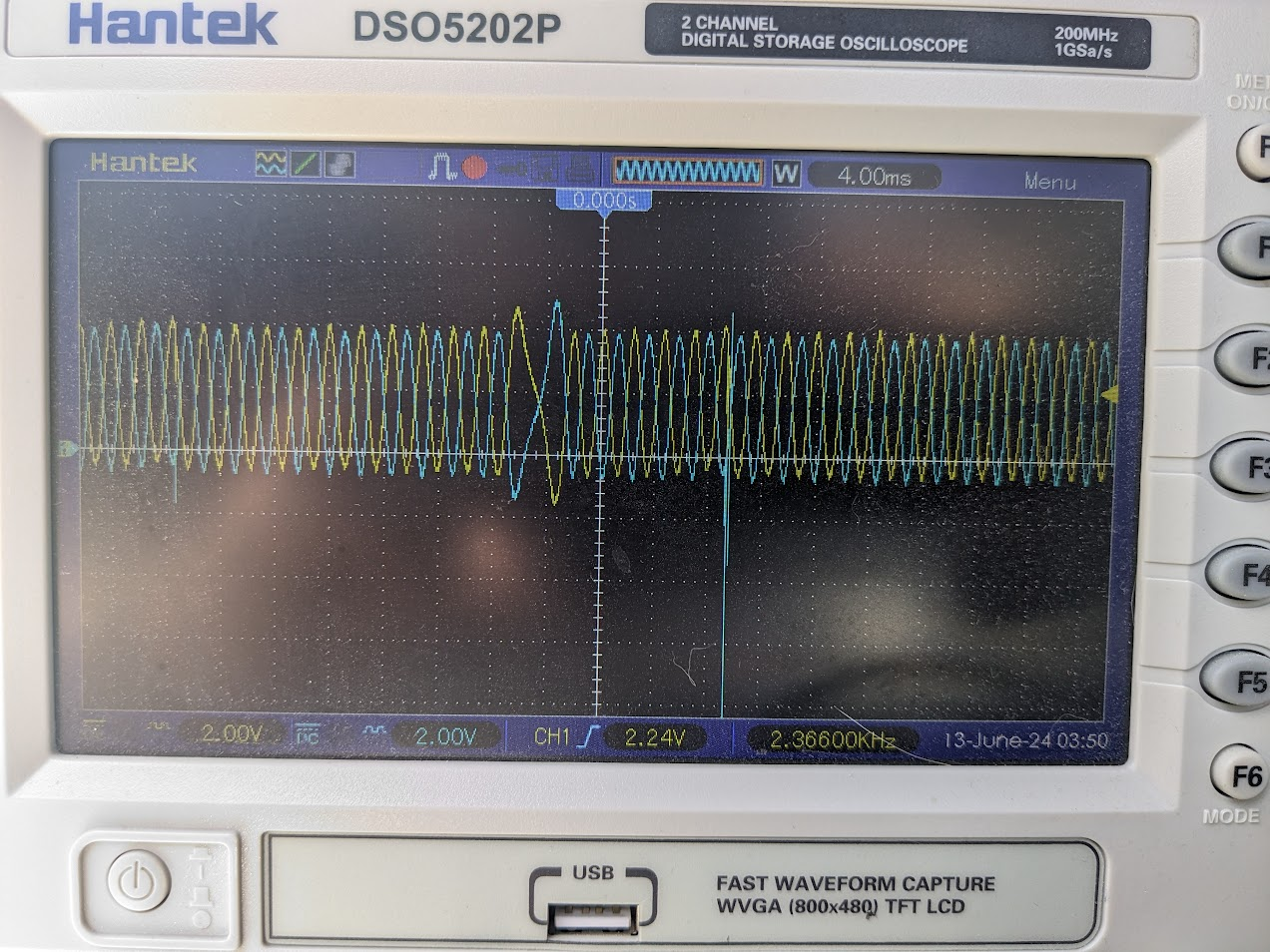
It seems to produce a sine wave (or 2 - 180 degrees out of phase if measured to ground as shown) with a cycle every ~34 cycles which has higher amplitude and lower frequency. My understanding is that the CKP is simply a coil of wire which faces the back side of the crank pulley which has some magnets in a radial pattern.. something like this:

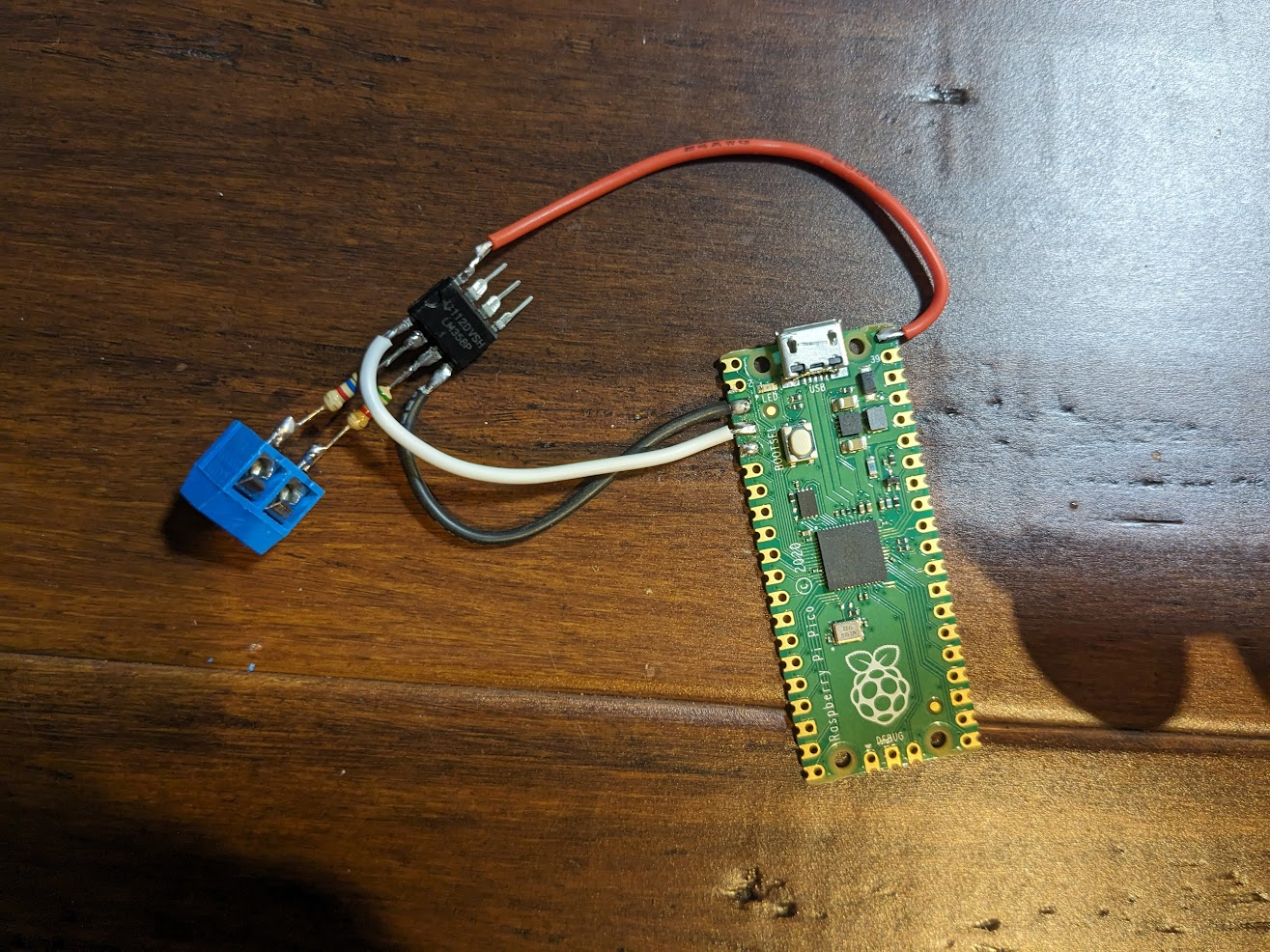
To capture the CKP signal, I used an op-amp comparator which will trigger an interrupt on a microcontroller:
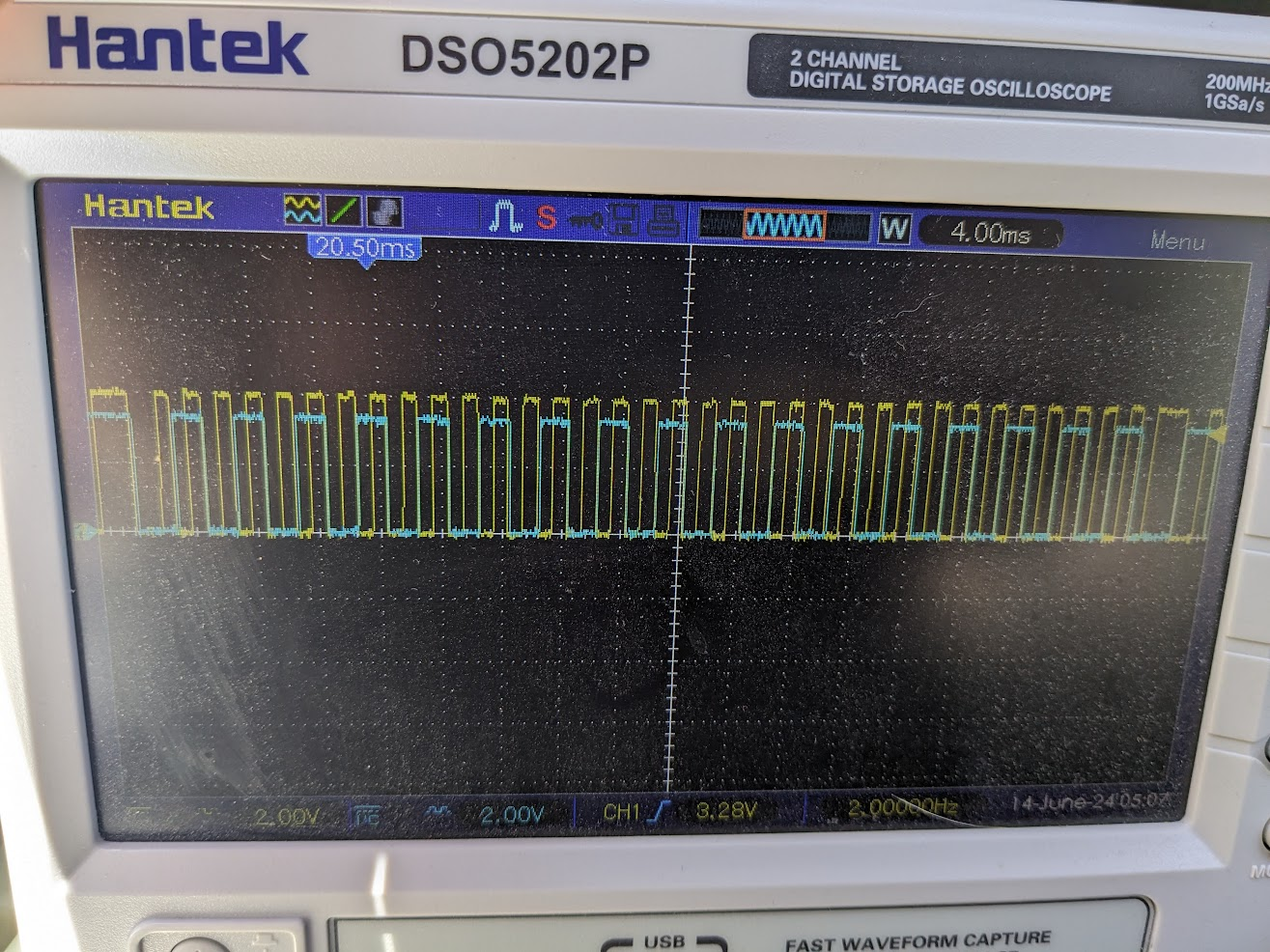
Each time the interrupt is triggered, the microcontroller will determine the time elapsed since the last interrupt. A rolling average will be kept of these interrupts, and if a pulse takes more than ~twice as long as the average then it will be considered the top-dead-center (TDC) pulse (note: I have no idea if the longer pulse is actually at TDC, but it might be… The important thing is that is happens once per revolution). The TDC pulse won’t be included in the average, this way, I can use the average to calculate the engine RPM, and the TDC pulse to keep the system in-phase with the engine.
Here are the pulses from the optocoupler in yellow and the test pulses produced by the microcontroller to match (blue), the microcontroller is programmed to toggle it’s output on each falling edge. This proves the microcontroller is capturing each pulse correctly and the ISR is running:
The injector is switched with a low side N-FET with it’s gate driven directly by a microcontroller GPIO. Through testing I verified that 200 HZ PWM provides good atomization across it’s full range of duty cycle while still being able to consistently control the amount of water dispensed.